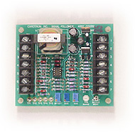
SIGNAL
FOLLOWER CARD
|
Model C10032-000 General Description Model C10032-000 Signal Follower Card is designed to handle a multiple of applications in which signal conditioning is required without input or output isolation. Voltage signals from 0 to 1 VDC through 0 to 100 VDC can be accepted on the input and calibrated for 0 to 10 VDC or 4 to 20 mA on the output. Current signals such as 1 to 5 mA or 4 to 20 mA can be used as inputs and converted to 0 to 10 VDC or 4 to 20 mA on the output. A +15 VDC supply is available on the input terminal strip to source a 10,000 Ohm potentiometer that can also be used as an input reference source. Positive or negative inputs can be applied to the C10032-000 Signal Follower Card. The polarity of the output will be the same as the input signal. A terminal is also provided for an optional Summing Input. The Summing Input is inverted and summed with the main input to modify the output. Calibration is made simply by the use of three board mounted 20 turn potentiometers. The OFFSET pot. sets the null point with the minimum input from the reference source. The BIAS pot. sets the minimum output level desired with minimum input. The GAIN sets the maximum output level when maximum input is received from the reference source. An optional external Trim potentiometer can be used to trim the output manually or via a dancer. An on board single turn Trim Range pot. sets the range of trim available from the external Trim pot. Specifications
|
|
Dimensions and Connections
Application Examples |
Microcon Technologies Inc.
1105 Crestlawn Drive, Unit # D8 & D9
Mississauga, Ontario L4W 1A7 Canada
Tel: (905) 602-4770
Fax: (905) 602-4779
|
|