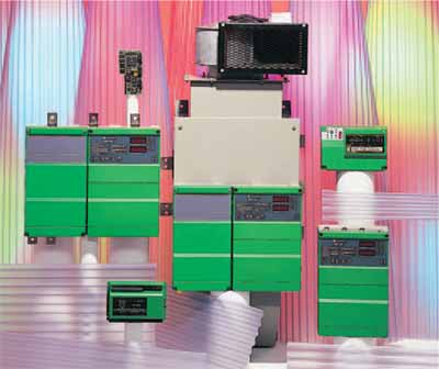
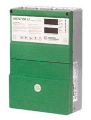
|

Overview
DC drives are widely used in
applications that require
regeneration, precise speed control, dynamic performance, and constant
torque over wide speed ranges. The Mentor II
delivers the universal DC drive solution.
Simple stand-alone applications are easily configured to control motor
speed, voltage or current using standard internal settings. Set-up is
convenient using the drive keypad, CTKP remote keypad, or MentorSoft, a
Windows™ based drive configuration tool. The Mentor II has extensive
diagnostic and communication abilities that enhance system reliability. The
drive’s standard yet powerful microprocessor is a versatile system
component that can eliminate the need for a PLC with integral functions
such as thresholds, timers and logic gates that perform basic control.
The simple addition of the MD29, a 32-bit application
co-processor card, provides high performance drive systems
with local intelligence for true distributed control. The MD29
enables users to incorporate custom or proprietary process
control application programs to their drive. The Mentor II also
provides a wide range of communication protocol options.
Mentor II systems have proven to be extremely reliable and
are ideally suited to web handling, winders, slitters, extruders, wire
drawing, converting lines, and plastics production. The Mentor II’s
integrated design and highly programmable features make it an ideal
choice for OEMs and System Integrators, as well as replacement or
retrofit drives for End Users.
|
 |
|
|
| Simple
Operation |
Easy
set up of the drive can be done using the main control
panel or via a standard communications interface from a
host computer.
Fast configuration of standard applications can be
achieved using 10 parameters or less. |
|
| Faster
Drive Set-Up |
| Programming
the Mentor II has never been easier. Designed to save
commissioning time, the drive has easily assimilated
function menus browsed and edited via five navigator
keys. |
|
| Better
Control |
| A
comprehensive self-tuning algorithm gives improved
current loop performance for a more uniform response at
all speeds. Drive performance is also enhanced with full
PID digital speed control. |
|
| More
Functions |
| The
main circuit board has been developed to incorporate
many additional features as standard. |
|
| Massive
Systems Potential |
| All
analogue inputs and most of the digital control inputs
are user-configurable, making Mentor II a true systems
drive having more versatility and flexibility than ever
before. |
|
| Wide
Ranging, More Flexible Communications |
| Mentor
II is able to communicate directly with PLCs and host
computers or via optional interface cards. This is
achieved with the standard RS485 port. |
|
| Digital
Speed and Position Loop |
| This
allows several drives to be run in speed or position synchronization. |
|
| Centre winder |
| The
drive torque is continuously adjusted to compensate for
changing coil diameter, machine losses and coil inertia. |
|
| Shaft
Orientation |
| This
allows the user to specify the final position of the
motor shaft relative to an electronic feedback datum,
for example a marker pulse from an encoder. The position
is adjusted by simply changing the value of the
appropriate parameter. |
|
| 'S'
Ramp |
| This
facility provides a curved function at each of a user
defined acceleration/deceleration ramp. |
| Mentor
II Specifications |
| |
Environment |
| Ambient Operating Temperature |
0 to 40°C Derate current 1.5% per
°C to 55°C |
| Cooling Method |
Convection and forced convection,
model dependent |
| Humidity |
95% non-condensing at 40°C |
| Storage Temperature |
-40 to 55°C |
| Altitude |
0 to 4000m Derate 1% per 100m
between 1000m and 4000m |
| Enclosure |
Chassis (IP00) |
| |
AC Supply Requirements |
| Voltage |
208 to 480 VAC -5% +10%
525/575/660 VAC ±10% (Optional M350 and above) |
| Phase |
3Ø |
| Frequency |
45 to 62 Hz |
| Efficiency |
98% |
| |
Control |
| Feedback Methods |
Armature Voltage (resolution 0.83
volts)
DC Tachometer (resolution 0.1%)
Encoder (resolution .01%) |
| Field Control |
Current regulated 8 Amps max
(M210/M210R and smaller)
Voltage regulated .675 or .9 X Line-to-line
voltage (M350/M350R and larger) |
| Analog Input Resolution |
12 bit (Qty 1), 10 bit (Qty 4) |
| Serial Communications |
4-wire RS422 or RS485
optically-isolated Protocol is ANSI x 3.28-2.5-A4
Baud rate is 4800 or 9600 |
| |
Protection |
| AC Line Under voltage Trip |
180 VAC |
| MOV Voltage Transient Protection |
Input transient suppression |
| Instantaneous Overcurrent Trip |
300% armature current |
| Armature Open Circuit |
Armature circuit is open |
| Drive Overload Trip |
Inverse time, 150% for 30 seconds |
| Phase Loss Trip |
Loss of input phase |
| Overtemperature Trip |
Heatsink exceeds 100°C |
| Motor Thermal Trip |
Motor over-temp switch or
Thermistor |
| Feedback Loss |
Loss of motor feedback |
| Feedback Reversal |
Tachometer or Encoder wired
backwards |
| Field Loss |
No field current |
| Field On |
Field current during auto-tune |
| Field Overcurrent |
Field current greater than field
demand |
| Current Loop Loss |
Loss of 4-20 mA reference |
| External Power Supply |
Short circuit on +24 VDC user
power supply |
| Power Supply |
Internal power supply out of
tolerance |
| Serial Communications |
Mode 3 serial comms data loss Loss |
| Processor 1 |
Main control processor fault
Watchdog lap |
| Processor 2 Watchdog Trip |
Second control processor fault
(MD29) |
| Hardware Fault |
Hardware malfunction on control
board |
| Memory Fault |
Stored parameter checksum fault |
| External Trip |
User interlock fault (programmed) |
| Software Fault (A29) |
MD29 software fault |
| |
Approvals & Listings |
| UL, cUL |
File #E58592 Vol. 5C Section 1 |
| CE |
Designed for marking |
| ISO 9001:2000 |
Certified Manufacturing Facility |
| ISO 14001 |
Certified Manufacturing Facility |

|
|
|

|
|
 |
Wide
range of network communication options |
 |
User
configurable analogue and digital drive inputs |
 |
Easy
to use PC configuration, Software: Mentor soft |
 |
Regeneration
up to 1.15 x VRMS |
 |
Available
in single and four quadrant |
 |
Armature
voltage, tacho or encoder feedback with loss detection |
 |
Phase
sequence tolerant with loss detection |
 |
0.025%
resolution for analogue speed demand |
 |
0.1%
speed holding for 100% load change with tacho feedback |
 |
On-board
field control with loss detection |
 |
150%
overload capacity for 30 seconds with motor overload
protection |
 |
Taper
current limit |
|
|

